Entity-relationship diagrams
A picture of the things a system stores and how they relate. Old, small, and still the fastest way to find out that two people mean different things by the word "order".
9 min readER - crow's foot1 of 3
The short answer
- Conceptual names entities and relationships only; logical adds attributes, keys and resolved many-to-many; physical adds types and indexes for one engine.
- A primary key identifies a row in its own table; a foreign key holds another table's primary key and is what actually implements a relationship.
- An ER diagram has no operations and its relationships map onto foreign keys. A class diagram models behaviour and can express what a schema cannot.
- Crow's foot is the de facto standard and what nearly every modern tool draws. Chen notation says the same thing with more space.

01What it shows#
An ER diagram describes the things a system stores and the connections between them. Three ingredients, and no more:
| Element | Notation | What it means |
|---|---|---|
| Entity | a named box | A kind of thing worth storing. Singular noun - Customer, not Customers - because a box represents the type and each row is one of them. |
| Attribute | a row inside the box | A fact about the entity. In crow's foot notation these live inside the box; in the older Chen notation they hang off it in ovals. |
| Relationship | A connection, with its cardinality drawn on each end. The symbols say how many of the entity at that end can take part. |
The value is almost entirely in the third one. Everybody can list the entities in their domain; the argument starts at "can an order exist without a customer?", and an ER diagram forces that question to be answered in a symbol rather than left comfortably vague in a document.
02Keys are the part that matters#
Attributes are easy. Keys are where an ER model earns its place, because a key is a claim about identity - and identity is where domain misunderstandings hide.
| Element | Notation | What it means |
|---|---|---|
| Primary key (PK) | marked PK, listed first | The attribute, or set of attributes, that identifies one row. Every entity has exactly one. |
| Foreign key (FK) | marked FK | An attribute holding another entity's key. Every relationship line corresponds to a foreign key somewhere, on the "many" side. |
| Natural key | a real-world attribute | An ISBN, an IBAN, an email address. Meaningful, and hostage to the outside world changing its mind. |
| Surrogate key | generated id | A number or UUID with no meaning. Stable by construction, and the default choice in most systems for exactly that reason. |
| Composite key | two or more attributes | Identity that needs more than one column. Common on junction entities, where the pair of foreign keys is the identity. |
03Cardinality, briefly#
Each end of a relationship carries two symbols: the outer one says how many and the inner one says whether it is optional. A bar is one, a crow's foot is many, and a circle is zero.
| Element | Notation | What it means |
|---|---|---|
| Exactly one | Bar, bar. Mandatory and single at both ends. | |
| Zero or one | Circle then bar. Optional and single. | |
| One or more | Bar then crow's foot. Mandatory and multiple. | |
| Zero or more | Circle then crow's foot. The most common end in practice. |
The symbol is read at the end nearest the entity it constrains, which is the opposite of what most people guess.
That last point catches nearly everyone, and it has an article of its own - crow's foot notation - covering which end is which, identifying versus non-identifying relationships, and how to resolve a many-to-many.
04Conceptual, logical, physical#
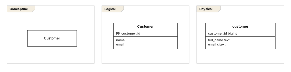
Most confused ER diagrams are two levels wearing one coat. Deciding which you are drawing settles a dozen small arguments before they start.
| Element | Notation | What it means |
|---|---|---|
| Conceptual | boxes and lines only | Entities and relationships in the business's own words. No keys, no types, often no attributes. Fits on one page, and is the one a stakeholder reviews. |
| Logical | attributes and keys, no types | Normalized, keyed, and independent of any particular database. Many-to-many relationships resolved. This is the design. |
| Physical | tables, columns, types | Named the way the database names things, with types, indexes, and whatever denormalization the workload actually justifies. |
You do not always need all three. A small service can go straight to logical. What never works is showing a conceptual diagram to a developer who needs the physical one, or a physical one to a business stakeholder who wanted to check whether a customer can have two addresses.
05ER diagram or class diagram?#
They look similar and mean different things. A class diagram describes types in a program: behaviour, inheritance, visibility, navigability. An ER diagram describes data at rest: keys, cardinality, and referential integrity. The overlap is real, and so is the divergence.
| Element | Notation | What it means |
|---|---|---|
| Operations | class diagram only | Entities have no methods. Rows do not do things. |
| Keys | ER only | A class diagram has object identity for free; a database has to be told what identity is. |
| Inheritance | class diagram natively | ER models it as a supertype-subtype structure, and the physical model has to pick one of three table layouts to implement it. |
| Many-to-many | drawable in both | A class diagram can leave it as one line forever. A logical ER model must resolve it into a junction entity, because a database cannot store it otherwise. |
Reach for it when
- The subject is what gets stored, and the audience includes a DBA
- You need to settle optionality and cardinality precisely
- The output is a schema, a migration, or a set of constraints
- A business stakeholder has to confirm the domain vocabulary
Reach for something else when
- The subject is behaviour or a type hierarchy - use a class diagram
- You are documenting an API's payloads rather than storage
- The store has no schema and the shape genuinely varies per document
- It is three tables and the DDL is shorter than the diagram
06Common mistakes#
- Plural entity names.
Customeris the entity;customersis the table. Mixing them makes relationship sentences unreadable. - Unresolved many-to-many in a logical model. No database can store it. Resolve it and name the junction entity after what it means -
Enrolment, notStudentCourse. - Every relationship optional. A model where nothing is mandatory encodes no rules at all, and the constraints end up scattered through application code instead.
- Attributes that are really entities.If "address" needs five sub-fields and can occur twice, it is an entity.
- Modelling reporting tables. A denormalized read model belongs in the physical model with a note saying why, not in the logical one where it will be mistaken for the domain.
In one line each
- 01Entities, attributes, relationships - and the relationships are where the value is.
- 02A key is a claim about identity; prefer surrogate keys and constrain the natural one.
- 03Cardinality is read at the end nearest the entity it constrains.
- 04Conceptual, logical and physical answer different questions for different people.
- 05A class diagram describes types in a program; an ER diagram describes data at rest.
- 06Read every line aloud in both directions - the cheapest review that exists.
07Common questions#
What is an entity-relationship diagram?
A picture of the things a system stores and how they relate: entities as boxes, their attributes inside, and lines between them carrying cardinality. It is the standard way to agree on a data model before any table exists.
What is the difference between conceptual, logical and physical data models?
A conceptual model names entities and relationships and nothing else, so it is a shared vocabulary. A logical model adds attributes, keys and resolved many-to-many relationships while staying independent of any database. A physical model adds types, indexes and whatever one specific engine needs.
What is the difference between a primary key and a foreign key?
A primary key identifies a row uniquely within its own table. A foreign key is a column holding a primary key value from another table, and it is what actually implements a relationship in a relational database.
How is an ER diagram different from a UML class diagram?
An ER diagram models stored data, so it has no operations and its relationships map onto foreign keys. A class diagram models types with behaviour and can express things a relational schema cannot, such as interfaces and polymorphism. Both often describe the same domain without matching element for element.
What notation should I use for ER diagrams?
Crow's foot is the de facto standard and is what nearly every modern tool draws. Chen notation, which puts relationships in diamonds, is still common in textbooks. What you can express is essentially the same either way, and crow's foot is more compact.
In this series
- 01ER diagrams
- 02Crow's foot notation
- 03Schema design
Related reading
Notation reference
Modelling practice
Structure diagrams
Structure diagrams
Structure diagrams
Modelling practice