Diagramy entít a vzťahov
Obraz vecí, ktoré systém ukladá, a toho, ako spolu súvisia. Starý, malý a stále najrýchlejší spôsob, ako zistiť, že dvaja ľudia myslia slovom "objednávka" niečo iné.
9 min čítaniaER - crow's foot1 z 3
Krátka odpoveď
- Konceptuálny model pomenúva len entity a vzťahy; logický pridáva atribúty, kľúče a rozložené mnoho k mnohým; fyzický typy a indexy pre jeden stroj.
- Primárny kľúč identifikuje riadok vo vlastnej tabuľke; cudzí kľúč drží primárny kľúč inej tabuľky a je to on, čo vzťah naozaj implementuje.
- ER diagram nemá operácie a jeho vzťahy sa mapujú na cudzie kľúče. Diagram tried modeluje správanie a vie vyjadriť to, čo schéma nedokáže.
- Vraňa noha je de facto štandard a kreslí ju takmer každý moderný nástroj. Chenova notácia hovorí to isté a zaberie viac miesta.

01Čo ukazuje#
ER diagram popisuje veci, ktoré systém ukladá, a spojenia medzi nimi. Tri zložky, a viac nie:
| Prvok | Notácia | Čo znamená |
|---|---|---|
| Entita | pomenovaný box | Druh veci, ktorý sa oplatí ukladať. Podstatné meno v jednotnom čísle - Customer, nie Customers - lebo box predstavuje typ a každý riadok je jedným z nich. |
| Atribút | riadok vnútri boxu | Fakt o entite. V notácii vranej nohy žijú vnútri boxu; v staršej Chenovej notácii z neho visia v ovaloch. |
| Vzťah | Spojenie, s kardinalitou nakreslenou na každom konci. Symboly hovoria, koľko entít na tom konci sa môže zúčastniť. |
Hodnota je takmer celá v tej tretej. Entity vo svojej doméne vymenuje každý; spor sa začne pri otázke „môže objednávka existovať bez zákazníka?“ - a ER diagram túto otázku núti zodpovedať symbolom namiesto toho, aby zostala pohodlne vágna v dokumente.
02Kľúče sú tá časť, na ktorej záleží#
Atribúty sú ľahké. Kľúče sú miesto, kde si ER model zaslúži svoje miesto, lebo kľúč je tvrdenie o identite - a práve v identite sa skrývajú doménové nedorozumenia.
| Prvok | Notácia | Čo znamená |
|---|---|---|
| Primárny kľúč (PK) | označený PK, uvedený prvý | Atribút alebo množina atribútov, ktorá identifikuje jeden riadok. Každá entita má práve jeden. |
| Cudzí kľúč (FK) | označený FK | Atribút držiaci kľúč inej entity. Každej čiare vzťahu zodpovedá niekde cudzí kľúč, a to na strane „veľa“. |
| Prirodzený kľúč | atribút zo skutočného sveta | ISBN, IBAN, e-mailová adresa. Zmysluplný - a rukojemník toho, že si vonkajší svet veci rozmyslí. |
| Náhradný kľúč | generované id | Číslo alebo UUID bez významu. Stabilný z konštrukcie, a práve preto vo väčšine systémov predvolená voľba. |
| Zložený kľúč | dva a viac atribútov | Identita, ktorá potrebuje viac než jeden stĺpec. Bežná na väzobných entitách, kde dvojica cudzích kľúčov je tou identitou. |
03Kardinalita, v krátkosti#
Každý koniec vzťahu nesie dva symboly: vonkajší hovorí koľko a vnútorný či je to nepovinné. Čiarka je jeden, vrania noha je veľa a krúžok je nula.
| Prvok | Notácia | Čo znamená |
|---|---|---|
| Práve jeden | Čiarka, čiarka. Povinné a jednotlivé na oboch koncoch. | |
| Nula alebo jeden | Krúžok a potom čiarka. Nepovinné a jednotlivé. | |
| Jeden alebo viac | Čiarka a potom vrania noha. Povinné a viacnásobné. | |
| Nula alebo viac | Krúžok a potom vrania noha. V praxi najčastejší koniec. |
Symbol sa číta na konci najbližšie k entite, ktorú obmedzuje, čo je opak toho, čo väčšina ľudí háda.
Práve tento posledný bod nachytá takmer každého a má vlastný článok - notácia vranej nohy - o tom, ktorý koniec je ktorý, o identifikujúcich verzus neidentifikujúcich vzťahoch a o tom, ako vyriešiť vzťah M:N.
04Konceptuálny, logický, fyzický#
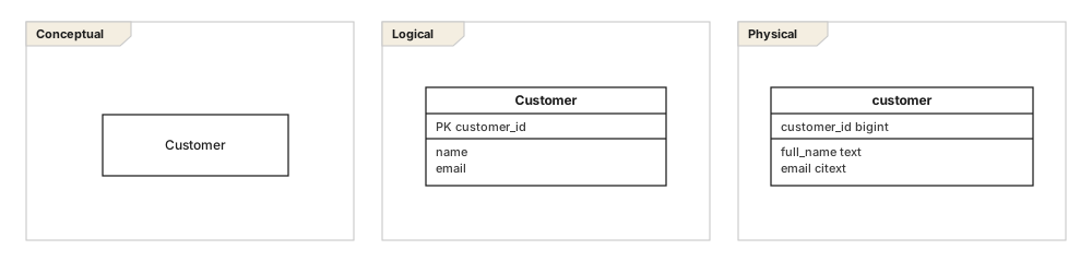
Väčšina zmätených ER diagramov sú dve úrovne v jednom kabáte. Rozhodnúť, ktorú kreslíte, urovná tucet malých sporov skôr, než začnú.
| Prvok | Notácia | Čo znamená |
|---|---|---|
| Konceptuálny | len boxy a čiary | Entity a vzťahy vlastnými slovami biznisu. Žiadne kľúče, žiadne typy, často ani atribúty. Zmestí sa na jednu stranu a je to ten, ktorý reviduje stakeholder. |
| Logický | atribúty a kľúče, bez typov | Normalizovaný, okľúčovaný a nezávislý od konkrétnej databázy. Vzťahy M:N vyriešené. Toto je návrh. |
| Fyzický | tabuľky, stĺpce, typy | Pomenované tak, ako pomenúva veci databáza, s typmi, indexmi a s takou denormalizáciou, akú si záťaž naozaj vyžaduje. |
Nie vždy potrebujete všetky tri. Malá služba môže ísť rovno na logický. Čo nikdy nefunguje, je ukázať konceptuálny diagram vývojárovi, ktorý potrebuje fyzický - alebo fyzický biznisovému stakeholderovi, ktorý chcel overiť, či zákazník môže mať dve adresy.
05ER diagram, alebo diagram tried?#
Vyzerajú podobne a znamenajú niečo iné. Diagram tried popisuje typy v programe: správanie, dedenie, viditeľnosť, navigovateľnosť. ER diagram popisuje dáta v pokoji: kľúče, kardinalitu a referenčnú integritu. Prekryv je skutočný a rozdiel takisto.
| Prvok | Notácia | Čo znamená |
|---|---|---|
| Operácie | len diagram tried | Entity nemajú metódy. Riadky nič nerobia. |
| Kľúče | len ER | Diagram tried má identitu objektu zadarmo; databáze treba povedať, čo je identita. |
| Dedenie | diagram tried natívne | ER to modeluje ako štruktúru nadtyp-podtyp a fyzický model si musí vybrať jedno z troch rozložení tabuliek, ako to implementovať. |
| Vzťah M:N | nakresliteľný v oboch | Diagram tried ho môže nechať ako jednu čiaru navždy. Logický ER model ho musí vyriešiť väzobnou entitou, lebo databáza ho inak uložiť nevie. |
Siahnite po ňom, keď
- Predmetom je to, čo sa ukladá, a v publiku je aj DBA
- Potrebujete presne rozhodnúť nepovinnosť a kardinalitu
- Výstupom je schéma, migrácia alebo množina obmedzení
- Biznisový stakeholder má potvrdiť doménový slovník
Siahnite po niečom inom, keď
- Predmetom je správanie alebo hierarchia typov - použite diagram tried
- Dokumentujete payloady API, nie úložisko
- Úložisko nemá schému a tvar sa naozaj líši dokument od dokumentu
- Sú to tri tabuľky a DDL je kratšie než diagram
06Časté chyby#
- Entity v množnom čísle.
Customerje entita;customersje tabuľka. Ich miešanie robí vety o vzťahoch nečitateľnými. - Nevyriešený vzťah M:N v logickom modeli. Žiadna databáza ho neuloží. Vyriešte ho a väzobnú entitu pomenujte podľa toho, čo znamená -
Enrolment, nieStudentCourse. - Každý vzťah nepovinný. Model, v ktorom nie je nič povinné, nekóduje žiadne pravidlá a obmedzenia potom skončia rozsypané po aplikačnom kóde.
- Atribúty, ktoré sú v skutočnosti entity. Ak „adresa“ potrebuje päť podpolí a môže sa vyskytnúť dvakrát, je to entita.
- Modelovanie reportovacích tabuliek. Denormalizovaný čítací model patrí do fyzického modelu s poznámkou prečo, nie do logického, kde si ho niekto pomýli s doménou.
Po jednom riadku na každé
- 01Entity, atribúty, vzťahy - a hodnota je vo vzťahoch.
- 02Kľúč je tvrdenie o identite; uprednostnite náhradné kľúče a prirodzený obmedzte.
- 03Kardinalita sa číta na konci najbližšie k entite, ktorú obmedzuje.
- 04Konceptuálny, logický a fyzický odpovedajú na iné otázky iným ľuďom.
- 05Diagram tried popisuje typy v programe; ER diagram popisuje dáta v pokoji.
- 06Prečítajte každú čiaru nahlas v oboch smeroch - najlacnejšia revízia, aká existuje.
07Časté otázky#
Čo je diagram entít a vzťahov?
Obraz vecí, ktoré systém ukladá, a toho, ako spolu súvisia: entity ako rámčeky, ich atribúty vnútri a čiary medzi nimi nesúce kardinalitu. Je to štandardný spôsob, ako sa dohodnúť na dátovom modeli skôr, než vznikne akákoľvek tabuľka.
Aký je rozdiel medzi konceptuálnym, logickým a fyzickým dátovým modelom?
Konceptuálny model pomenúva entity a vzťahy a nič viac, je teda zdieľaným slovníkom. Logický model pridáva atribúty, kľúče a rozložené vzťahy typu mnoho k mnohým, pričom zostáva nezávislý od databázy. Fyzický model pridáva typy, indexy a čokoľvek, čo si vyžaduje jeden konkrétny stroj.
Aký je rozdiel medzi primárnym a cudzím kľúčom?
Primárny kľúč jednoznačne identifikuje riadok vnútri vlastnej tabuľky. Cudzí kľúč je stĺpec, ktorý drží hodnotu primárneho kľúča inej tabuľky, a práve on v relačnej databáze skutočne implementuje vzťah.
Čím sa ER diagram líši od UML diagramu tried?
ER diagram modeluje uložené dáta, takže nemá operácie a jeho vzťahy sa mapujú na cudzie kľúče. Diagram tried modeluje typy so správaním a vie vyjadriť veci, ktoré relačná schéma nedokáže, napríklad rozhrania a polymorfizmus. Oba často popisujú tú istú doménu bez toho, aby si zodpovedali prvok po prvku.
Akú notáciu použiť pre ER diagramy?
Vraňa noha je de facto štandard a je to to, čo kreslí takmer každý moderný nástroj. Chenova notácia, ktorá dáva vzťahy do kosoštvorcov, je stále bežná v učebniciach. To, čo sa dá vyjadriť, je v podstate rovnaké v oboch, a vraňa noha je kompaktnejšia.
V tejto sérii
- 01ER diagramy
- 02Notácia vranej nohy
- 03Návrh schémy
Súvisiace články
Prehľad notácie
Prax modelovania
Diagramy štruktúry
Diagramy štruktúry
Diagramy štruktúry
Prax modelovania