UML deployment diagrams
What runs where. Nodes, the artifacts deployed onto them, and the connections between - the diagram an infrastructure review, a security review, or a 3am incident actually needs.
7 min readUML 2.5.121 of 35
The short answer
- Artifacts get deployed onto nodes; nodes are never deployed onto anything. A JAR is an artifact, the JVM running it is a node.
- A device is hardware, an execution environment is software that hosts other software. Both are nodes, and the environment nests inside the device.
- The plain line between nodes is a communication path. Label it with the protocol - that label is what makes the diagram useful in a security review.
- This is not an informal architecture picture. Nodes, artifacts, deploy and communication paths have defined semantics, so two readers agree on the claim.
01What it shows#
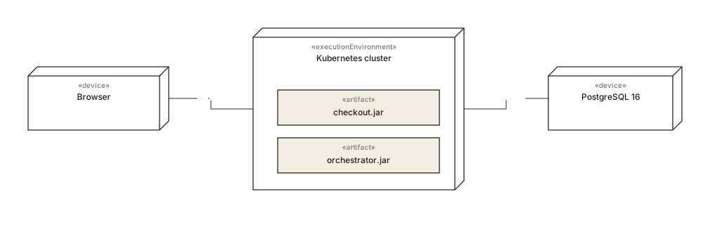
A deployment diagram maps software onto hardware. It is the only UML diagram that talks about the physical world - machines, containers, network links - and it answers a question no other diagram can: if this box catches fire, what stops working?
It is also the diagram most likely to be asked for by somebody who is not a developer. Security reviews, disaster-recovery plans, data-residency questions and cost conversations all start from "where does this actually run, and what talks to what".
02Nodes, artifacts, paths#
| Element | Notation | What it means |
|---|---|---|
| Node | 3D box | Something that computes or stores. The general case; the two stereotypes below narrow it. |
| Device | 3D box, «device» | Physical hardware: a server, a phone, a load balancer, a database host. |
| Execution environment | 3D box, «executionEnvironment» | Software that hosts other software: a JVM, a container runtime, a Kubernetes cluster, a serverless platform. |
| Artifact | rectangle, «artifact» | A physical file that gets deployed: a jar, an image, a binary, a config file. Named like the real file. |
| Deployment | nesting, or a «deploy» arrow | This artifact runs on that node. Drawing it inside is clearer than an arrow when it fits. |
| Communication path | plain solid line | Two nodes can talk. Label it with the protocol and port - that is where the value is. |
03How much detail#
Deployment diagrams rot faster than any other kind, because infrastructure changes weekly and diagrams do not. The way to keep one useful is to draw it at the altitude that changes slowly.
Draw the topology, not the inventory."Kubernetes cluster" stays true for years. "Three m5.large instances in eu-central-1b" is wrong by next quarter and belongs in the infrastructure-as-code repository, which is the only place it can be correct.
Label the links. A line saying nothing is nearly worthless; a line saying TCP 5432, HTTPS, or AMQP over TLSis what a security reviewer reads the diagram for. The same goes for trust boundaries - if a link crosses from your network to somebody else's, say so.
Draw multiplicity where it matters. A node can carry a multiplicity just as a class can. Writing 1..* on the application node and 1 on the database says something real about the system's failure modes.
04When to draw one#
Reach for it when
- Security or compliance review - what crosses which boundary, over what protocol
- Disaster recovery and failure analysis - what is single, what is redundant
- Onboarding somebody who has to operate the system, not just change it
- Data residency questions: which data sits in which jurisdiction
Reach for something else when
- The whole system is one process on one machine
- Your infrastructure-as-code already describes it and is actually read
- You mean logical services and contracts - use a component diagram
- It would need updating every sprint to stay true
05Common mistakes#
- Unlabelled communication paths.The protocol and port are the content. Without them the line says only "these are connected".
- Components drawn where artifacts belong. Nodes host files. Put
checkout.jaron the node and keepCheckouton the component diagram. - Instance detail that cannot stay true. Hostnames and instance sizes belong in code, not in a diagram.
- No trust boundaries.If some nodes are yours and some are a third party's, that distinction is usually the most important thing on the page.
- One diagram for every environment. Draw production. Note the differences in text; do not draw four near-identical diagrams that will diverge.
In one line each
- 01The only UML diagram about physical reality: what runs where, and what talks to what.
- 02Nodes execute or store; «device» is hardware, «executionEnvironment» is hosting software.
- 03Artifacts are files - jars, images, binaries - and nesting them in a node means deployed there.
- 04Always label communication paths with the protocol and port.
- 05Draw the topology, which changes slowly; leave the inventory to infrastructure-as-code.
- 06Mark trust boundaries - that is what reviewers came for.
06Common questions#
What is the difference between a node and an artifact?
A node is hardware or an execution environment: a server, a container, a JVM. An artifact is a physical file produced by development, such as a JAR, an image or a config file. Artifacts get deployed onto nodes; nodes are never deployed onto anything.
What is the difference between a device and an execution environment?
Both are nodes. A device is physical or virtual hardware, marked with the device keyword. An execution environment is software that hosts other software, such as an application server or a container runtime, and is normally drawn nested inside the device that runs it.
What is a communication path?
The plain line between two nodes, meaning they can exchange messages. It is usually labelled with the protocol or network, which is what makes a deployment diagram useful in an infrastructure or security review.
Is a deployment diagram the same as an architecture diagram?
No. Most so-called architecture diagrams are informal boxes and arrows. A deployment diagram is a UML structure diagram with defined semantics: nodes, artifacts, the deploy relationship and communication paths, which means two people reading it agree on what it claims.
In this series
- 01What is UML?
- 02UML symbols
- 03Choosing a diagram
- 04Class diagrams
- 05Class diagram examples
- 06How to draw a class diagram
- 07Class diagram symbols
- 08Sequence diagrams
- 09Sequence diagram examples
- 10How to draw a sequence diagram
- 11Use case diagrams
- 12Use case examples
- 13Activity diagrams
- 14Activity examples
- 15State machine diagrams
- 16State machine examples
- 17Component diagrams
- 18Component examples
- 19Drawing a component diagram
- 20Component symbols
- 21Deployment diagrams
- 22Deployment examples
- 23Object diagrams
- 24Package diagrams
- 25Composite structure diagrams
- 26Communication diagrams
- 27Sequence vs communication
- 28Timing diagrams
- 29Interaction overview diagrams
- 30Profile diagrams
- 31UML with AI
- 32E-commerce example
- 33Banking example
- 34Microservices example
- 35AWS example
Related reading
Foundations
Structure diagrams
Structure diagrams
Structure diagrams
Structure diagrams
Structure diagrams