Ein Komponentendiagramm zeichnen
Sechs Schritte von der leeren Fläche zu einem Diagramm, das man einem Team geben kann, an einem kleinen System gezeigt. Die Reihenfolge zählt mehr als die Notation: Teile, dann Zusagen, dann Bedarfe, dann die Prüfungen, die eine falsche Grenze finden, bevor jemand darauf baut.
8 Min. LesezeitUML 2.5.119 von 35
Die kurze Antwort
- Listen Sie die Teile auf, die man plausibel kaufen oder ersetzen statt bauen könnte, und hören Sie bei neun auf. Diese Frage wählt die Kästen, nicht die Ordnerstruktur.
- Erst Komponenten, als Kästen ohne Pfeile. Die Verträge benennen Sie danach, wenn Sie wissen, welches Teil auf welcher Seite steht.
- So detailliert, dass sich aus der Umgebung eines Kastens dessen Ersatz bauen liesse. Methodensignaturen gehören in den Code, nicht hierher.
- Fertig, wenn jede Komponente eine Schnittstelle trägt, kein Pfeil auf eine Komponente statt auf einen Vertrag zeigt und ein zugehaltener Kasten trotzdem spezifizierbar bleibt.

01Schritt 1. Listen Sie auf, was ersetzbar wäre#
Bevor Sie irgendetwas zeichnen, schreiben Sie eine Liste. Nicht Ihrer Module, nicht Ihrer Ordner - der Teile des Systems, die man plausibel austauschen könnte: gekauft statt gebaut, von einem anderen Team neu geschrieben oder von jemand anderem betrieben.
Diese Frage ist der ganze Filter. Ein Ordner ist keine Komponente und eine Klasse auch nicht; ein Ding mit einer Grenze, das man einem Lieferanten übergeben könnte, schon. Das Reporting-System in diesem Artikel ergab vier: ein Dashboard, einen Scheduler, der Berichte über Nacht laufen lässt, den Report-Service selbst und einen Adapter, der mit dem Data Warehouse spricht.
02Schritt 2. Zeichnen Sie die Kästen, und keine Pfeile#
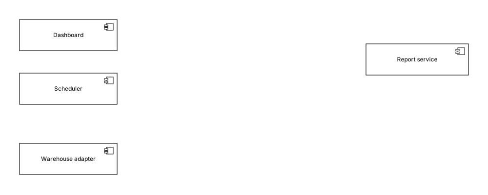
Platzieren Sie die Teile und widerstehen Sie dem Verbinden. Jetzt Pfeile zu zeichnen heisst, sie zwischen Komponenten zu ziehen, und eine Linie vom Dashboard direkt zum Report-Service sagt nur „diese beiden sind irgendwie beteiligt“ - genau die Unschärfe, zu deren Beseitigung ein Komponentendiagramm existiert.
Das Layout ist hier dreissig Sekunden wert: Verbraucher auf die eine Seite, Anbieter auf die andere. Jedes Diagramm dieser Reihe ist von links nach rechts gezeichnet, mit Abhängigkeiten in eine Richtung, weil ein Leser die Richtung dann auf einen Blick prüft statt jeder Linie zu folgen.
03Schritt 3. Benennen Sie, was jedes Teil anbietet#

Fragen Sie bei jedem Kasten, worauf sich jemand von aussen verlassen darf, und benennen Sie das. Hier IReports und IWarehouse - ein Vertrag pro Fähigkeit, nicht einer pro Verbraucher. Verbinden Sie ihn mit einer Realisierung: gestrichelte Linie, hohles Dreieck, auf die Schnittstelle zeigend.
In diesem Schritt passiert der eigentliche Entwurf, und genau ihn überspringen die Leute. Einen Vertrag zu benennen zwingt zur Entscheidung, was öffentlich ist, und der Streit, der folgt - „gehört der CSV-Export zu IReports oder nicht?“ - ist der Streit, den man führen sollte, bevor zwei Teams ihn im Code unterschiedlich beantworten.
04Schritt 4. Ergänzen Sie, was jedes Teil benötigt#
Nun die zweite Hälfte, und die trägt die Information: welche Verträge braucht jede Komponente? Zeichnen Sie eine Abhängigkeit - gestrichelte Linie, offene Pfeilspitze - von der Komponente zur benötigten Schnittstelle. Das Ergebnis ist das Diagramm am Anfang dieses Artikels.
In dem Moment, in dem diese Pfeile landen, werden zwei Dinge sichtbar. Dashboard und Scheduler zeigen beide auf IReports, eine Änderung daran ist also sichtbar eine Änderung für zwei Verbraucher. Und der Report-Service zeigt auf IWarehouse statt auf den Adapter, der Adapter ist also austauschbar, ohne dass der Dienst es merkt - entweder war das Ihre Absicht, oder es ist eine Entdeckung, die man jetzt machen sollte.
05Schritt 5. Vier Prüfungen#
Ein Komponentendiagramm ist fertig, wenn es diese übersteht. Sie dauern eine Minute, und jede hat öfter ein echtes Problem gefunden als sauber durchgelaufen zu sein.
- Halten Sie einen Kasten mit der Hand zu. Was übrig bleibt - die daran hängenden Schnittstellen - ist die Spezifikation seines Ersatzes. Müsste ein Ersatz etwas wissen, das nicht auf dem Bildschirm steht, liegt die Grenze falsch.
- Folgen Sie den Pfeilen auf der Suche nach einem Zyklus. Zwei Komponenten, die einander benötigen, lassen sich nicht unabhängig ausliefern, testen oder ersetzen. Das letzte der durchgearbeiteten Beispiele zeigt, wie das aussieht und wie man es aufbricht.
- Prüfen Sie, dass jede Komponente mindestens eine Schnittstelle hat. Ein Kasten ohne alles ist entweder keine Komponente oder für dieses Diagramm nicht relevant.
- Lesen Sie die Schnittstellennamen laut. Ist einer nach seinem aktuellen Anbieter statt nach seiner Fähigkeit benannt -
IMainframeBillingstattIBilling-, steckt der Lieferant im Vertrag, und der Tausch, den das Diagramm verspricht, wird nicht so sauber wie er aussieht.
06Schritt 6. Löschen Sie, was auf ein anderes Diagramm gehört#
Dazu greifen, wenn
- Schnittstellen, und welche Komponente auf welcher Seite jeder einzelnen steht
- Stereotypen, die die Beschaffung eines Teils ändern - «subsystem», «service», «library»
- Ports, wenn eine Komponente wirklich zwei getrennte Oberflächen hat
- Eine Notiz an jeder umstrittenen Grenze, die sagt, wer sie entschieden hat
Zu etwas anderem greifen, wenn
- Server, Regionen, Container und Prozesse - Verteilungsdiagramm
- Klassen, Felder und Methoden innerhalb einer Komponente - Klassendiagramm
- Die Aufrufreihenfolge zwischen Komponenten - Sequenzdiagramm
- Datenbanktabellen und -spalten - ER-Diagramm
Die rechte Spalte ist keine Pedanterie über Diagrammarten. Jeder Punkt darauf macht das Bild grösser, ohne die Frage zu beantworten, für die das Diagramm gezeichnet wurde, und jeder gibt ihm einen zweiten Grund zu veralten: ein Komponentendiagramm übersteht einen Plattformwechsel unberührt, dieselbe Zeichnung mit zwei AWS-Regionen darauf nicht.
In je einer Zeile
- 01Listen Sie auf, was ersetzbar wäre. Diese Liste, nicht der Ordnerbaum, ist Ihre Komponentenliste.
- 02Erst Kästen, keine Pfeile - eine Linie zwischen zwei Komponenten sagt nichts Prüfbares.
- 03Benennen Sie die angebotenen Verträge vor den benötigten; dort liegen die Entwurfsentscheidungen.
- 04Benötigte Schnittstellen tragen die Abhängigkeitsinformation und sind die Hälfte, die weggelassen wird.
- 05Halten Sie einen beliebigen Kasten zu: was bleibt, muss seinen Ersatz vollständig spezifizieren.
- 06Alles über Maschinen, Klassen oder Aufrufreihenfolge gehört auf ein anderes Diagramm.
Ist die Zeichnung fertig, steht die Referenz zu jedem Zeichen darauf in Komponentendiagramm-Symbole, und die weitere Begründung, wann diese Diagrammart den Aufwand überhaupt lohnt, im Leitfaden zum Komponentendiagramm.
07Häufige Fragen#
Wie fange ich ein Komponentendiagramm an?
Beginnen Sie mit einer Liste der Teile, die man plausibel ersetzen oder kaufen statt bauen könnte, und hören Sie bei neun auf. Diese Frage entscheidet, welche Kästen ins Diagramm gehören - nicht die Ordnerstruktur - und sie zuerst zu beantworten verhindert, dass eine Zeichnung des Repositorys entsteht.
Was kommt zuerst, Komponenten oder Schnittstellen?
Zuerst Komponenten, aber nur als Kästen ohne Pfeile. Die Verträge zu benennen ist der schwierige Teil, und ihn als zweites zu tun heisst, sie zu benennen, während man weiss, welche Teile auf beiden Seiten stehen, statt eine Schnittstelle zu erfinden und dann etwas dafür zu suchen.
Wie detailliert soll ein Komponentendiagramm sein?
So detailliert, dass jemand aus der Umgebung eines Kastens dessen Ersatz bauen könnte, und keinen Deut mehr. Operationen und Parameter gehören in die Schnittstellendefinition oder in den Code - ein Diagramm, das Methodensignaturen auflistet, ist eine Woche später veraltet.
Woran erkenne ich, dass ein Komponentendiagramm fertig ist?
Wenn jede Komponente mindestens eine Schnittstelle trägt, kein Pfeil auf eine Komponente statt auf einen Vertrag zeigt, und das Zuhalten eines beliebigen Kastens immer noch genug übrig lässt, um dessen Ersatz zu spezifizieren. Gelten alle drei, sagt das Diagramm etwas Prüfbares und Sie können aufhören.
In dieser Reihe
- 01Was ist UML?
- 02UML-Symbole
- 03Diagramm auswählen
- 04Klassendiagramme
- 05Klassendiagramm-Beispiele
- 06Klassendiagramm zeichnen
- 07Klassendiagramm-Symbole
- 08Sequenzdiagramme
- 09Sequenzdiagramm-Beispiele
- 10Sequenzdiagramm zeichnen
- 11Anwendungsfalldiagramme
- 12Anwendungsfall-Beispiele
- 13Aktivitätsdiagramme
- 14Aktivitätsbeispiele
- 15Zustandsdiagramme
- 16Zustandsdiagramm-Beispiele
- 17Komponentendiagramme
- 18Komponenten-Beispiele
- 19Komponentendiagramm zeichnen
- 20Komponenten-Symbole
- 21Verteilungsdiagramme
- 22Verteilungsbeispiele
- 23Objektdiagramme
- 24Paketdiagramme
- 25Kompositionsstrukturdiagramme
- 26Kommunikationsdiagramme
- 27Sequenz vs Kommunikation
- 28Zeitverlaufsdiagramme
- 29Interaktionsübersichtsdiagramme
- 30Profildiagramme
- 31UML mit KI
- 32E-Commerce-Beispiel
- 33Banken-Beispiel
- 34Microservices-Beispiel
- 35AWS-Beispiel
Passend dazu
Strukturdiagramme
Strukturdiagramme
Notationsreferenz
Strukturdiagramme
Strukturdiagramme
Strukturdiagramme