Dessiner un diagramme de composants
Six étapes d'une page blanche à un diagramme que l'on peut remettre à une équipe, sur un petit système. L'ordre compte plus que la notation : les pièces, puis les promesses, puis les besoins, puis les vérifications qui repèrent une mauvaise frontière avant que quiconque construise dessus.
8 min de lectureUML 2.5.119 sur 35
La réponse courte
- Listez les pièces que l'on pourrait plausiblement acheter ou remplacer plutôt que construire, et arrêtez-vous à neuf. C'est cette question qui choisit les boîtes, pas l'arborescence.
- Les composants d'abord, en boîtes sans flèches. Nommez les contrats ensuite, quand vous savez déjà quelle pièce se tient de chaque côté.
- Assez détaillé pour qu'on puisse construire le remplaçant d'une boîte à partir de son entourage. Les signatures de méthodes vont dans le code, pas ici.
- Terminé quand chaque composant porte une interface, qu'aucune flèche ne vise un composant au lieu d'un contrat, et que masquer une boîte laisse de quoi spécifier son remplaçant.

01Étape 1. Listez ce qui pourrait être remplacé#
Avant de dessiner quoi que ce soit, faites une liste. Pas de vos modules, pas de vos dossiers : des parties du système que l'on pourrait plausiblement échanger contre une autre implémentation - achetées plutôt que construites, réécrites par une autre équipe, ou exploitées par quelqu'un d'autre.
Cette question est tout le filtre. Un dossier n'est pas un composant, une classe non plus ; une chose dotée d'une frontière que l'on pourrait confier à un fournisseur, si. Le système de reporting de cet article en a donné quatre : un tableau de bord, un ordonnanceur qui lance les rapports la nuit, le service de rapports lui-même, et un adaptateur qui parle à l'entrepôt de données.
02Étape 2. Dessinez les boîtes, et aucune flèche#
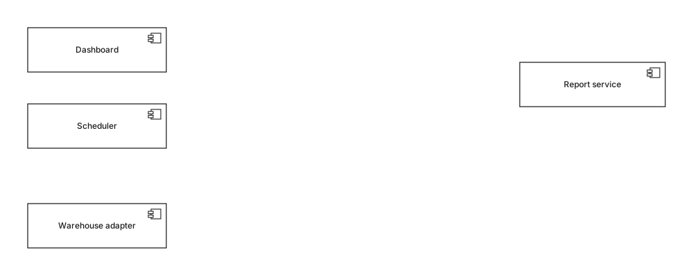
Placez les pièces et résistez à l'envie de les relier. Dessiner des flèches maintenant revient à les tracer entre composants, et un trait du Dashboard directement au service de rapports ne dit que « ces deux-là sont impliqués d'une manière ou d'une autre », c'est-à-dire exactement le flou qu'un diagramme de composants existe pour supprimer.
La mise en page vaut trente secondes ici : les consommateurs d'un côté, les fournisseurs de l'autre. Tous les diagrammes de cette série sont dessinés de gauche à droite, les dépendances allant dans un seul sens, parce que le lecteur vérifie alors la direction d'un coup d'œil plutôt qu'en suivant chaque trait.
03Étape 3. Nommez ce que chaque pièce fournit#

Pour chaque boîte, demandez-vous sur quoi quelqu'un d'extérieur a le droit de compter, et nommez-le. Ici IReports et IWarehouse - un contrat par capacité, pas un par consommateur. Rattachez-le par une réalisation : trait pointillé, triangle creux, pointant vers l'interface.
C'est à cette étape que se fait la vraie conception, et c'est l'étape que l'on saute. Nommer un contrat oblige à décider ce qui est public, et la dispute qui suit - « l'export CSV fait-il partie d'IReports ou non ? » - est celle qu'il vaut mieux avoir avant que deux équipes y répondent différemment dans le code.
04Étape 4. Ajoutez ce que chaque pièce requiert#
Vient la seconde moitié, celle qui porte l'information : de quels contrats chaque composant a-t-il besoin ? Tracez une dépendance - trait pointillé, pointe ouverte - du composant vers l'interface qu'il requiert. Le résultat est le diagramme en tête de cet article.
Deux choses deviennent visibles dès que ces flèches se posent. Le tableau de bord et l'ordonnanceur pointent tous deux vers IReports : le modifier est désormais visiblement un changement pour deux consommateurs. Et le service de rapports pointe vers IWarehouse et non vers l'adaptateur, donc l'adaptateur est remplaçable sans que le service s'en aperçoive - ce qui est soit ce que vous vouliez, soit une découverte qu'il vaut mieux faire maintenant.
05Étape 5. Passez quatre vérifications#
Un diagramme de composants est terminé quand il y survit. Elles prennent une minute, et chacune a plus souvent attrapé un vrai problème qu'elle n'est passée sans rien dire.
- Masquez une boîte avec la main. Ce qui reste - les interfaces qui y étaient rattachées - est la spécification de son remplaçant. Si ce remplaçant devait savoir quelque chose qui n'est pas à l'écran, la frontière est au mauvais endroit.
- Suivez les flèches à la recherche d'un cycle. Deux composants qui se requièrent mutuellement ne peuvent être déployés, testés ni remplacés indépendamment. Voyez le dernier des exemples détaillés pour ce à quoi cela ressemble et comment on le casse.
- Vérifiez que chaque composant a au moins une interface. Une boîte à laquelle rien n'est rattaché n'est pas un composant, ou n'a rien à faire sur ce diagramme.
- Lisez les noms d'interfaces à voix haute. Si l'un est nommé d'après son fournisseur actuel plutôt que d'après sa capacité -
IMainframeBillingau lieu d'IBilling- le contrat a le fournisseur cuit dedans, et l'échange que le diagramme promet ne sera pas aussi propre qu'il en a l'air.
06Étape 6. Supprimez ce qui relève d'un autre diagramme#
À utiliser quand
- Les interfaces, et quel composant se tient de quel côté de chacune
- Les stéréotypes qui changent la façon dont une pièce est acquise - «subsystem», «service», «library»
- Les ports, quand un composant a réellement deux surfaces distinctes
- Une note sur toute frontière contestée, disant qui l'a tranchée
Préférer autre chose quand
- Serveurs, régions, conteneurs et processus - diagramme de déploiement
- Classes, attributs et méthodes à l'intérieur d'un composant - diagramme de classes
- L'ordre des appels entre composants - diagramme de séquence
- Tables et colonnes de base de données - diagramme entité-association
La colonne de droite n'est pas du pédantisme sur les types de diagrammes. Chaque élément agrandit l'image sans répondre à la question pour laquelle le diagramme a été dessiné, et chacun lui donne une seconde raison de se périmer : un diagramme de composants traverse un changement de plateforme intact, le même dessin avec deux régions AWS dessus, non.
En une ligne chacun
- 01Listez ce qui pourrait être remplacé. Cette liste, pas l'arborescence des dossiers, est votre liste de composants.
- 02Les boîtes d'abord, aucune flèche : un trait entre deux composants n'affirme rien de vérifiable.
- 03Nommez les contrats fournis avant les contrats requis ; c'est là que sont les décisions de conception.
- 04Les interfaces requises portent l'information de dépendance et sont la moitié que l'on omet.
- 05Masquez n'importe quelle boîte : ce qui reste doit spécifier entièrement son remplaçant.
- 06Tout ce qui touche aux machines, aux classes ou à l'ordre des appels relève d'un autre diagramme.
Le dessin fait, la référence de chaque signe qui s'y trouve est dans les symboles du diagramme de composants, et l'argumentaire plus large sur les cas où ce type de diagramme vaut l'effort est dans le guide du diagramme de composants.
07Questions fréquentes#
Par où commencer un diagramme de composants ?
Commencez par lister les parties du système que l'on pourrait plausiblement remplacer ou acheter plutôt que construire, et arrêtez-vous à neuf. C'est cette question, et non l'arborescence des dossiers, qui décide des boîtes à dessiner, et y répondre d'abord évite de produire une image du dépôt.
Que dessine-t-on en premier, les composants ou les interfaces ?
Les composants d'abord, mais seulement comme des boîtes sans flèches. Nommer les contrats est la partie difficile, et la faire ensuite permet de les nommer en sachant quelles pièces se tiennent de part et d'autre, au lieu d'inventer une interface puis de chercher quoi mettre derrière.
Quel niveau de détail pour un diagramme de composants ?
Assez de détail pour que quelqu'un puisse construire le remplaçant de n'importe quelle boîte à partir de ce qui l'entoure, et pas davantage. Les opérations et les paramètres relèvent de la définition d'interface ou du code : un diagramme qui liste des signatures est périmé la semaine suivante.
Comment savoir qu'un diagramme de composants est terminé ?
Quand chaque composant porte au moins une interface, qu'aucune flèche ne vise un composant au lieu d'un contrat, et que masquer n'importe quelle boîte laisse encore de quoi spécifier son remplaçant. Si les trois tiennent, le diagramme énonce quelque chose de vérifiable et vous pouvez vous arrêter.
Dans cette série
- 01Qu'est-ce que UML ?
- 02Symboles UML
- 03Choisir un diagramme
- 04Diagrammes de classes
- 05Exemples de diagrammes de classes
- 06Dessiner un diagramme de classes
- 07Symboles du diagramme de classes
- 08Diagrammes de séquence
- 09Exemples de diagrammes de séquence
- 10Dessiner un diagramme de séquence
- 11Diagrammes de cas d'utilisation
- 12Exemples de cas d'utilisation
- 13Diagrammes d'activité
- 14Exemples d'activité
- 15Diagrammes états-transitions
- 16Exemples d'états-transitions
- 17Diagrammes de composants
- 18Exemples de composants
- 19Dessiner un diagramme de composants
- 20Symboles de composants
- 21Diagrammes de déploiement
- 22Exemples de déploiement
- 23Diagrammes d'objets
- 24Diagrammes de paquetages
- 25Diagrammes de structure composite
- 26Diagrammes de communication
- 27Séquence vs communication
- 28Diagrammes de temps
- 29Diagrammes globaux d'interaction
- 30Diagrammes de profil
- 31UML avec l'IA
- 32Exemple e-commerce
- 33Exemple bancaire
- 34Exemple microservices
- 35Exemple AWS
À lire aussi
Diagrammes de structure
Diagrammes de structure
Référence de notation
Diagrammes de structure
Diagrammes de structure
Diagrammes de structure