Ako nakresliť diagram komponentov
Šesť krokov od prázdneho plátna po diagram, ktorý sa dá odovzdať tímu, na jednom malom systéme. Poradie je dôležitejšie než notácia: časti, potom sľuby, potom potreby a nakoniec kontroly, ktoré odhalia zlú hranicu skôr, než na nej niekto začne stavať.
8 min čítaniaUML 2.5.119 z 35
Krátka odpoveď
- Vypíšte časti, ktoré by sa reálne dali kúpiť alebo vymeniť namiesto postaviť, a zastavte sa pri deviatich. Boxy vyberá táto otázka, nie štruktúra priečinkov.
- Najskôr komponenty, ako boxy bez šípok. Zmluvy pomenujte až potom, keď už viete, ktorá časť stojí na ktorej strane.
- Taký podrobný, aby sa z okolia ktoréhokoľvek boxu dala postaviť jeho náhrada. Signatúry metód patria do kódu, nie sem.
- Hotový je vtedy, keď každý komponent nesie rozhranie, žiadna šípka nemieri na komponent namiesto zmluvy a zakrytie ktoréhokoľvek boxu stále zadá jeho náhradu.

01Krok 1. Vypíšte, čo by sa dalo vymeniť#
Skôr než čokoľvek nakreslíte, spíšte zoznam. Nie svojich modulov, nie svojich priečinkov - častí systému, ktoré by sa reálne dali vymeniť za inú implementáciu: kúpené namiesto postavené, prepísané iným tímom alebo prevádzkované niekým iným.
Práve táto otázka je celý filter. Priečinok nie je komponent a trieda tiež nie; vec s hranicou, ktorú by ste vedeli odovzdať dodávateľovi, áno. Reportovací systém v tomto článku ich dal štyri: dashboard, plánovač, ktorý spúšťa reporty cez noc, samotnú službu reportov a adaptér, ktorý hovorí s dátovým skladom.
02Krok 2. Nakreslite boxy a žiadne šípky#
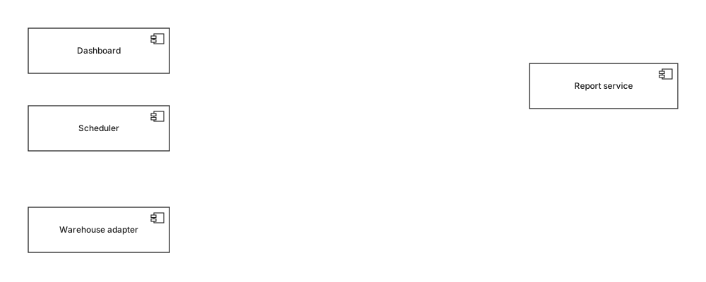
Umiestnite časti a odolajte pokušeniu spojiť ich. Kresliť šípky teraz znamená kresliť ich medzi komponentmi a čiara z Dashboardu rovno do Služby reportov hovorí len „tieto dva sú nejako zapojené“, čo je práve tá vágnosť, ktorú diagram komponentov existuje odstrániť.
Rozloženie tu stojí za tridsať sekúnd: dajte spotrebiteľov na jednu stranu a poskytovateľov na druhú. Každý diagram v tejto sérii je kreslený zľava doprava, so závislosťami tečúcimi jedným smerom, lebo potom čitateľ overí smer pohľadom namiesto sledovania každej čiary.
03Krok 3. Pomenujte, čo každá časť poskytuje#

Pri každom boxe sa spýtajte, na čo sa smie spoľahnúť niekto zvonka, a to pomenujte. Tu IReports a IWarehouse - jedna zmluva na schopnosť, nie jedna na spotrebiteľa. Pripojte ju realizáciou: prerušovaná čiara, prázdny trojuholník, mieriaci na rozhranie.
Práve v tomto kroku sa deje skutočný návrh a práve tento krok ľudia preskakujú. Pomenovanie zmluvy vás núti rozhodnúť, čo je verejné, a hádka, ktorá nasleduje - „patrí export do CSV do IReports, alebo nie?“ - je hádka, ktorú sa oplatí zviesť skôr, než na ňu dva tímy odpovedia v kóde rozdielne.
04Krok 4. Doplňte, čo každá časť vyžaduje#
Teraz druhá polovica a tá, ktorá nesie informáciu: ktoré zmluvy každý komponent potrebuje? Nakreslite závislosť - prerušovaná čiara, otvorený hrot - z komponentu na rozhranie, ktoré vyžaduje. Výsledok je diagram na začiatku článku.
Vo chvíli, keď tie šípky dopadnú, sa zviditeľnia dve veci. Dashboard aj plánovač mieria na IReports, takže jeho zmena je teraz viditeľne zmenou pre dvoch spotrebiteľov. A služba reportov mieri na IWarehouse, nie na adaptér, takže adaptér sa dá vymeniť bez toho, aby si to služba všimla - čo je buď to, čo ste zamýšľali, alebo objav, ktorý stojí za to urobiť teraz.
05Krok 5. Spustite štyri kontroly#
Diagram komponentov je hotový, keď ich prežije. Zaberú minútu a každá z nich odhalila skutočný problém častejšie, než prešla načisto.
- Zakryte box dlaňou. To, čo zostane - rozhrania, ktoré k nemu boli pripojené - je zadanie jeho náhrady. Ak by náhrada musela vedieť niečo, čo na obrazovke nie je, hranica je na nesprávnom mieste.
- Sledujte šípky, či nevznikol cyklus. Dva komponenty, ktoré vyžadujú jeden druhý, sa nedajú nasadzovať, testovať ani vymieňať nezávisle. Posledný z rozobratých príkladov ukazuje, ako to vyzerá a ako sa to rozbije.
- Overte, že každý komponent má aspoň jedno rozhranie. Box, ku ktorému nič nie je pripojené, buď nie je komponent, alebo pre tento diagram nie je podstatný.
- Prečítajte názvy rozhraní nahlas. Ak je niektoré pomenované podľa svojho súčasného poskytovateľa namiesto podľa schopnosti -
IMainframeBillingnamiestoIBilling- má zmluva dodávateľa zapečeného v sebe a výmena, ktorú diagram sľubuje, nebude taká čistá, ako vyzerá.
06Krok 6. Zmažte, čo patrí na iný diagram#
Siahnite po ňom, keď
- Rozhrania a to, ktorý komponent stojí na ktorej strane každého z nich
- Stereotypy, ktoré menia spôsob obstarania časti - «subsystem», «service», «library»
- Porty, keď má komponent naozaj dva oddelené povrchy
- Poznámku pri každej spornej hranici s tým, kto o nej rozhodol
Siahnite po niečom inom, keď
- Servery, regióny, kontajnery a procesy - diagram nasadenia
- Triedy, atribúty a metódy vnútri komponentu - diagram tried
- Poradie volaní medzi komponentmi - sekvenčný diagram
- Databázové tabuľky a stĺpce - ER diagram
Pravý stĺpec nie je pedantéria o druhoch diagramov. Každá položka v ňom zväčší obrázok bez toho, aby odpovedala na otázku, kvôli ktorej bol diagram nakreslený, a každá dá diagramu druhý dôvod zastarať: diagram komponentov prežije zmenu platformy nedotknutý a tá istá kresba s dvoma AWS regiónmi nie.
Po jednom riadku na každé
- 01Vypíšte, čo by sa dalo vymeniť. Ten zoznam, nie strom priečinkov, je vaším zoznamom komponentov.
- 02Najprv boxy, žiadne šípky - čiara medzi dvoma komponentmi netvrdí nič overiteľné.
- 03Pomenujte poskytované zmluvy skôr než vyžadované; práve tam sú návrhové rozhodnutia.
- 04Vyžadované rozhrania nesú informáciu o závislostiach a sú tou polovicou, ktorú ľudia vynechávajú.
- 05Zakryte ktorýkoľvek box: to, čo zostane, musí úplne zadať jeho náhradu.
- 06Čokoľvek o strojoch, triedach alebo poradí volaní patrí na iný diagram.
Keď je kresba hotová, referenciu na každú značku na nej nájdete v článku symboly diagramu komponentov, a širšie zdôvodnenie, kedy sa tento druh diagramu vôbec oplatí, v sprievodcovi diagramom komponentov.
07Časté otázky#
Ako začať diagram komponentov od nuly?
Začnite zoznamom častí systému, ktoré by sa reálne dali vymeniť alebo kúpiť namiesto postaviť, a zastavte sa pri deviatich. Práve táto otázka, nie štruktúra priečinkov, rozhoduje o tom, ktoré boxy na diagram patria, a odpovedať na ňu ako prvú je to, čo zabráni, aby z kresby vznikol obrázok repozitára.
Čo je prvé, komponenty alebo rozhrania?
Najskôr komponenty, ale len ako boxy bez šípok. Pomenovať zmluvy je tá ťažká časť a robiť ju druhú znamená pomenovať ich s vedomím, ktoré časti stoja na oboch stranách, namiesto vymyslenia rozhrania a následného hľadania niečoho, čo zaň postavíte.
Ako podrobný má diagram komponentov byť?
Taký podrobný, aby niekto dokázal z okolia postaviť náhradu ktoréhokoľvek boxu, a nič viac. Operácie a parametre patria do definície rozhrania alebo do kódu, nie na diagram - diagram, ktorý vypisuje signatúry metód, je zastaraný týždeň po nakreslení.
Podľa čoho spoznám, že je diagram komponentov hotový?
Keď má každý komponent aspoň jedno pripojené rozhranie, žiadna šípka nemieri na komponent namiesto na zmluvu a zakrytie ktoréhokoľvek boxu dlaňou stále nechá na obrazovke dosť na to, aby sa dala jeho náhrada zadať. Ak platí všetko troje, diagram tvrdí niečo overiteľné a môžete skončiť.
V tejto sérii
- 01Čo je UML?
- 02Symboly UML
- 03Výber diagramu
- 04Diagramy tried
- 05Príklady diagramov tried
- 06Ako nakresliť diagram tried
- 07Symboly diagramu tried
- 08Sekvenčné diagramy
- 09Príklady sekvenčných diagramov
- 10Ako nakresliť sekvenčný diagram
- 11Diagramy prípadov použitia
- 12Príklady prípadov použitia
- 13Diagramy aktivít
- 14Príklady aktivít
- 15Stavové diagramy
- 16Príklady stavových diagramov
- 17Diagramy komponentov
- 18Príklady komponentov
- 19Kreslenie diagramu komponentov
- 20Symboly komponentov
- 21Diagramy nasadenia
- 22Príklady nasadenia
- 23Diagramy objektov
- 24Diagramy balíkov
- 25Diagramy zloženej štruktúry
- 26Komunikačné diagramy
- 27Sekvenčný vs komunikačný
- 28Časové diagramy
- 29Diagramy prehľadu interakcií
- 30Diagramy profilov
- 31UML pomocou AI
- 32Príklad e-shopu
- 33Príklad banky
- 34Príklad mikroslužieb
- 35Príklad AWS
Súvisiace články
Diagramy štruktúry
Diagramy štruktúry
Prehľad notácie
Diagramy štruktúry
Diagramy štruktúry
Diagramy štruktúry