How to draw a component diagram
Six steps from an empty canvas to a diagram somebody could hand a team, drawn on one small system. The order matters more than the notation: parts, then promises, then needs, then the checks that catch a wrong boundary before anyone builds against it.
8 min readUML 2.5.119 of 35
The short answer
- List the parts that could plausibly be bought or replaced instead of built, and stop at nine. That question picks the boxes, not the folder structure.
- Components first, as boxes with no arrows. Name the contracts second, once you already know which part stands on each side of them.
- Detailed enough that somebody could build a replacement for any one box from what surrounds it. Method signatures belong in code, not here.
- It is finished when every component carries an interface, no arrow points at a component instead of a contract, and covering any box still specifies its replacement.

01Step 1. List what could be replaced#
Before drawing anything, write a list. Not of your modules, not of your folders - of the parts of the system that could plausibly be swapped for a different implementation: bought instead of built, rewritten by another team, or run by somebody else.
That question is the whole filter. A folder is not a component and neither is a class; a thing with a boundary somebody could hand to a supplier is. The reporting system in this article produced four: a dashboard, a scheduler that runs reports overnight, the report service itself, and an adapter that talks to the data warehouse.
02Step 2. Draw the boxes, and no arrows#
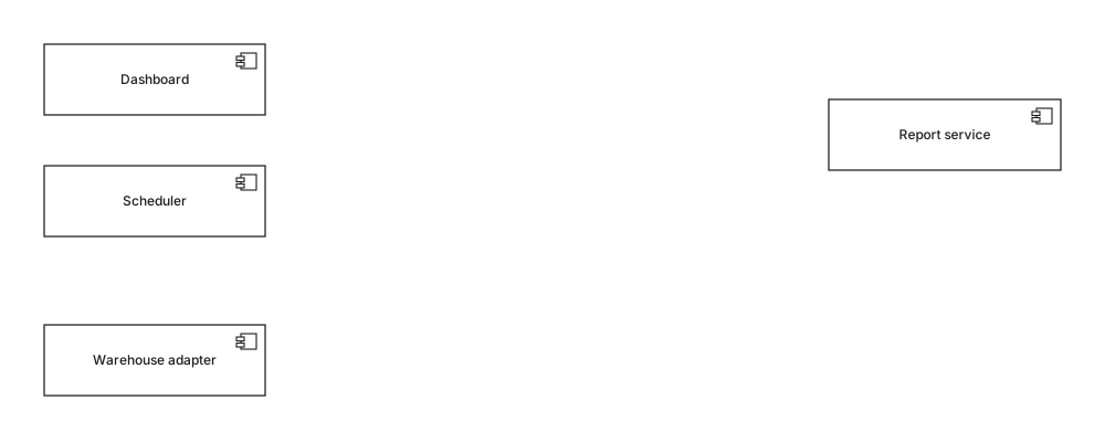
Place the parts and resist connecting them. Drawing arrows now means drawing them between components, and a line from Dashboard straight to Report service says only "these two are involved somehow", which is the vagueness a component diagram exists to remove.
Layout is worth thirty seconds here: put consumers on one side and providers on the other. Every diagram in this series is drawn left to right, dependencies flowing one way, because a reader can then check the direction at a glance rather than by following each line.
03Step 3. Name what each part provides#

For each box, ask what somebody outside it is allowed to rely on, and name that. IReports and IWarehouse here - one contract per capability, not one per consumer. Attach it with a realization: dashed line, hollow triangle, pointing at the interface.
This step is where the real design happens, and it is the step people skip. Naming a contract forces you to decide what is public, and the argument that follows - "is the CSV export part of IReports or not?" - is the argument worth having before two teams answer it differently in code.
04Step 4. Add what each part requires#
Now the second half, and the half that carries the information: for each component, which contracts does it need? Draw a dependency - dashed line, open arrowhead - from the component to the interface it requires. The finished result is the diagram at the top of this article.
Two things become visible the moment those arrows land. The dashboard and the scheduler both point at IReports, so changing it is now visibly a change to two consumers. And the report service points at IWarehouse rather than at the adapter, so the adapter is replaceable without the service noticing - which is either what you intended or a discovery worth making now.
05Step 5. Run four checks#
A component diagram is finished when it survives these. They take a minute and each one has caught a real problem more often than it has passed cleanly.
- Cover a box with your hand. What is left - the interfaces that were attached to it - is the specification of its replacement. If a replacement would need to know something that is not on screen, the boundary is in the wrong place.
- Follow the arrows for a cycle. Two components that require each other cannot be deployed, tested or replaced independently. See the last of the worked examples for what that looks like and how it gets broken.
- Check every component has at least one interface. A box with nothing attached is either not a component or not relevant to this diagram.
- Read the interface names aloud. If one is named after its current provider rather than its capability -
IMainframeBillingrather thanIBilling- the contract has the supplier baked into it, and the swap the diagram promises will not be as clean as it looks.
06Step 6. Delete what belongs on another diagram#
Reach for it when
- Interfaces, and which component is on which side of each
- Stereotypes that change how a part is procured - «subsystem», «service», «library»
- Ports, when one component genuinely has two separate surfaces
- A note on any boundary that is contested, saying who decided it
Reach for something else when
- Servers, regions, containers and processes - deployment diagram
- Classes, fields and methods inside a component - class diagram
- The call sequence between components - sequence diagram
- Database tables and columns - ER diagram
The right-hand column is not pedantry about diagram kinds. Every item on it makes the picture bigger without answering the question this diagram was drawn for, and each one gives the diagram a second reason to go out of date: a component diagram survives a re-platforming untouched, and the same drawing with two AWS regions on it does not.
In one line each
- 01List what could be replaced. That list, not the folder tree, is your component list.
- 02Boxes first, no arrows - a line between two components states nothing checkable.
- 03Name the provided contracts before the required ones; that is where the design decisions are.
- 04Required interfaces carry the dependency information and are the half people omit.
- 05Cover any box: what remains must fully specify its replacement.
- 06Anything about machines, classes or call order belongs on a different diagram.
With the drawing done, the reference for every mark on it is in component diagram symbols, and the wider case for when this diagram kind is worth the effort at all is in the component diagram guide.
07Common questions#
How do I start a component diagram from scratch?
Start by listing the parts of the system that could plausibly be replaced or bought instead of built, and stop the list at nine. That question, rather than the folder structure, is what decides which boxes belong on the diagram, and answering it first is what keeps the drawing from turning into a picture of the repository.
What comes first, the components or the interfaces?
Components first, but only as boxes with no arrows. Naming the contracts is the hard part and doing it second means you name them knowing which parts are on either side, rather than inventing an interface and then hunting for something to put behind it.
How detailed should a component diagram be?
Detailed enough that somebody could build a replacement for any one box from what is drawn around it, and no more. Operations and parameters belong in the interface definition or the code, not on the diagram, because a diagram that lists method signatures is out of date the week after it is drawn.
How do I know when a component diagram is finished?
When every component has at least one interface attached, no arrow points at a component instead of a contract, and covering any single box with your hand still leaves enough on screen to specify its replacement. If all three hold, the diagram says something checkable and you can stop.
In this series
- 01What is UML?
- 02UML symbols
- 03Choosing a diagram
- 04Class diagrams
- 05Class diagram examples
- 06How to draw a class diagram
- 07Class diagram symbols
- 08Sequence diagrams
- 09Sequence diagram examples
- 10How to draw a sequence diagram
- 11Use case diagrams
- 12Use case examples
- 13Activity diagrams
- 14Activity examples
- 15State machine diagrams
- 16State machine examples
- 17Component diagrams
- 18Component examples
- 19Drawing a component diagram
- 20Component symbols
- 21Deployment diagrams
- 22Deployment examples
- 23Object diagrams
- 24Package diagrams
- 25Composite structure diagrams
- 26Communication diagrams
- 27Sequence vs communication
- 28Timing diagrams
- 29Interaction overview diagrams
- 30Profile diagrams
- 31UML with AI
- 32E-commerce example
- 33Banking example
- 34Microservices example
- 35AWS example
Related reading
Structure diagrams
Structure diagrams
Notation reference
Structure diagrams
Structure diagrams
Structure diagrams