Deployment diagram examples
Three deployment diagrams of systems you will recognise - a three-tier web application, a Kubernetes cluster and a load-balanced pool - each with the reasoning for what was drawn and what was deliberately left off.
8 min readUML 2.5.122 of 35
The short answer
- Four nodes, three labelled communication paths and three deploy arrows is a complete diagram: browser, web server, application server, database.
- A running container is an execution environment and therefore a node. The image it started from is an artifact. Drawing the image as a node is the usual mistake.
- Show redundancy with a multiplicity such as 3..* on one node. A diagram claiming exactly three instances is wrong the moment it autoscales.
- Draw only enough to answer the question that made you draw it. Every extra node is a claim somebody has to keep true after the next migration.

01Example 1: a three-tier web application#
The diagram above is the one worth being able to draw from memory. A browser, a web server terminating TLS, an application server, a database. Three communication paths carrying the protocol and port, and three artifacts dropped onto the nodes that run them.
Two decisions in it are worth naming. First, the protocol labels are the reason the diagram is useful: HTTPS, HTTP/8080, TCP/5432 is the entire content of most security reviews, and a diagram without them is four boxes anybody could have guessed. Second, the artifacts are real filenames - orders.jar, not “application” - because a deployment diagram is about physical things, and a build produces files with names.
02Example 2: a Kubernetes cluster#
Containers make people hesitate, because a container is both a thing that runs and a thing that was built. UML already separates those: the running container is an execution environment, which is a node, and the image it started from is an artifact, which is deployed onto it.

Nothing about the shape of this diagram differs from the three-tier one, which is the point: the runtime changed and the notation did not. The load balancer is a «device» because it is infrastructure you do not deploy into. The ingress controller and the pod are «execution environment» because other things run inside them. The image tag orders:1.4.2is an artifact because a build produced it, and putting the version in the label is what makes the diagram answer “what is running in production right now”.
The managed database sits at the edge as a plain device. That is the honest drawing: you do not deploy artifacts onto a service somebody else operates, and pretending the schema is installed “onto RDS” is only true in the sense that it was applied there once.
03Example 3: a load-balanced pool#
The commonest reason anyone opens a deployment diagram is to find out what happens when one box dies. That question has a shape, and it is worth drawing explicitly rather than leaving it to a footnote.
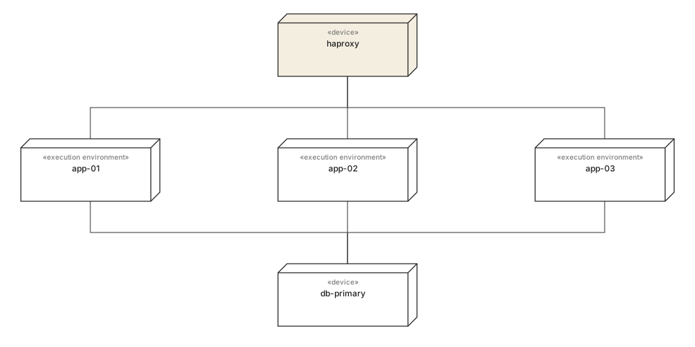
Three application nodes behind one load balancer, all writing to a single primary. Drawn this way, the single point of failure is visible without anybody having to say it: the app tier fans out and the data tier does not. That is a sentence somebody will act on, and it took no extra notation to make.
When the count varies at runtime, replace the three nodes with one carrying a multiplicity - app-node [3..*] - rather than drawing an arbitrary number. A diagram that claims exactly three is false the first time the group scales, and a diagram known to be false stops being consulted.
04What to leave off#
Every deployment diagram that becomes useless does so the same way: somebody kept adding nodes. The discipline is deciding what the diagram is for before the second box goes down.
Reach for it when
- Protocols and ports on every communication path - it is the content of most reviews.
- Real artifact names with versions, so the diagram answers what is running now.
- One representative instance per role, with a multiplicity when the count varies.
- Managed services as plain devices at the edge, with the boundary of what you operate visible.
Reach for something else when
- Logical layers - they have no address and nothing is deployed onto them.
- Every microservice in a large estate. Draw one subsystem per diagram instead.
- Monitoring, logging and CI agents, unless the diagram is about them.
- Live instance counts, which are wrong by the time the diagram is reviewed.
If you need the counterpart that shows the software rather than the machines, that is a component diagram. The two are usually drawn as a pair, and the deployment one is the shorter of them.
05What to remember#
In one line each
- 01Four nodes, labelled protocols and named artifacts is already a complete deployment diagram.
- 02A running container is a node; the image it started from is an artifact. Confusing the two is the usual container mistake.
- 03Protocol and port labels are what make the diagram worth opening in a review.
- 04Draw one instance per role and use a multiplicity when the count varies at runtime.
- 05If a box cannot be pinged, it does not belong on this diagram.
06Common questions#
What is a simple example of a deployment diagram?
A browser connecting to a web server, the web server to an application server, and the application server to a database, with one artifact deployed onto each. Four nodes, three communication paths labelled with their protocols, and three deploy arrows is a complete and useful diagram.
How do you draw a deployment diagram for Kubernetes?
Model the cluster's runtime pieces as nodes and the images as artifacts. The load balancer is a device, the ingress controller and each pod are execution environments, and the container image is an artifact deployed onto the pod. Managed services such as a hosted database stay devices at the edge of the diagram.
Are containers nodes or artifacts in UML?
Both, depending on which container you mean. A running container is an execution environment, which is a node, because other things run inside it. The image it was started from is an artifact, because it is a file produced by a build. Drawing the image as a node is the most common mistake on a container diagram.
How do you show redundancy on a deployment diagram?
Either draw the instances, which is honest and does not scale past about four, or draw one node and put a multiplicity on it, such as app-node with 3..* in the corner. Use the second when the count varies at runtime, since a diagram claiming exactly three is wrong the moment it autoscales.
How much detail belongs on a deployment diagram?
Enough to answer the question that made you draw it. An infrastructure review wants protocols and ports on the communication paths; an onboarding diagram wants the four boxes and nothing else. Every extra node is a claim somebody has to keep true after the next migration.
In this series
- 01What is UML?
- 02UML symbols
- 03Choosing a diagram
- 04Class diagrams
- 05Class diagram examples
- 06How to draw a class diagram
- 07Class diagram symbols
- 08Sequence diagrams
- 09Sequence diagram examples
- 10How to draw a sequence diagram
- 11Use case diagrams
- 12Use case examples
- 13Activity diagrams
- 14Activity examples
- 15State machine diagrams
- 16State machine examples
- 17Component diagrams
- 18Component examples
- 19Drawing a component diagram
- 20Component symbols
- 21Deployment diagrams
- 22Deployment examples
- 23Object diagrams
- 24Package diagrams
- 25Composite structure diagrams
- 26Communication diagrams
- 27Sequence vs communication
- 28Timing diagrams
- 29Interaction overview diagrams
- 30Profile diagrams
- 31UML with AI
- 32E-commerce example
- 33Banking example
- 34Microservices example
- 35AWS example
Related reading
Structure diagrams
Structure diagrams
Structure diagrams
Modelling practice
Structure diagrams
Structure diagrams