Příklady diagramů nasazení
Tři diagramy nasazení systémů, které znáte - třívrstvá webová aplikace, Kubernetes klastr a pool za load balancerem - vždy s odůvodněním, co bylo nakresleno a co záměrně vynecháno.
8 min čteníUML 2.5.122 z 35
Krátká odpověď
- Čtyři uzly, tři označené komunikační cesty a tři šipky nasazení jsou úplný diagram: prohlížeč, webový server, aplikační server, databáze.
- Běžící kontejner je vykonávací prostředí, a tedy uzel. Obraz, ze kterého byl spuštěn, je artefakt. Kreslit obraz jako uzel je obvyklá chyba.
- Redundanci ukažte násobností, například 3..* na jednom uzlu. Diagram tvrdící přesně tři instance je špatně hned po prvním autoškálování.
- Kreslete jen tolik, aby to odpovědělo na otázku, kvůli které jste kreslili. Každý další uzel je tvrzení, které musí někdo po další migraci udržet pravdivé.

01Příklad 1: třívrstvá webová aplikace#
Diagram výše je ten, který se vyplatí umět nakreslit zpaměti. Prohlížeč, webový server ukončující TLS, aplikační server, databáze. Tři komunikační cesty nesoucí protokol a port a tři artefakty položené na uzly, které je spouštějí.
Dvě rozhodnutí v něm stojí za pojmenování. Zaprvé, popisky protokolů jsou důvodem, proč je diagram užitečný: HTTPS, HTTP/8080, TCP/5432 je celým obsahem většiny bezpečnostních posudků a diagram bez nich jsou čtyři boxy, které by uhodl každý. Zadruhé, artefakty jsou skutečné názvy souborů - orders.jar, ne „aplikace“ - protože diagram nasazení je o fyzických věcech a build produkuje soubory se jmény.
02Příklad 2: cluster Kubernetes#
Kontejnery lidi znejišťují, protože kontejner je zároveň věc, která běží, i věc, která byla sestavená. UML ty dvě už odděluje: běžící kontejner je vykonávací prostředí, což je uzel, a image, ze kterého se spustil, je artefakt, který je na něj nasazený.

Tvar tohohle diagramu se nijak neliší od toho třívrstvého, a právě o to jde: změnilo se běhové prostředí a notace ne. Load balancer je «device», protože je to infrastruktura, do které nenasazujete. Ingress kontrolér a pod jsou «execution environment», protože uvnitř nich běží další věci. Tag image orders:1.4.2je artefakt, protože ho vyprodukoval build, a právě dát verzi do popisku je to, co dělá diagram schopným odpovědět na otázku „co běží právě teď v produkci“.
Spravovaná databáze sedí na okraji jako obyčejné zařízení. To je poctivá kresba: artefakty nenasazujete na službu, kterou provozuje někdo jiný, a předstírat, že schéma je nainstalované „na RDS“, je pravda jen v tom smyslu, že tam bylo jednou aplikované.
03Příklad 3: pool za load balancerem#
Nejčastějším důvodem, proč si někdo otevře diagram nasazení, je zjistit, co se stane, když jeden box umře. Ta otázka má tvar a vyplatí se ho nakreslit výslovně, ne ho nechat na poznámku pod čarou.
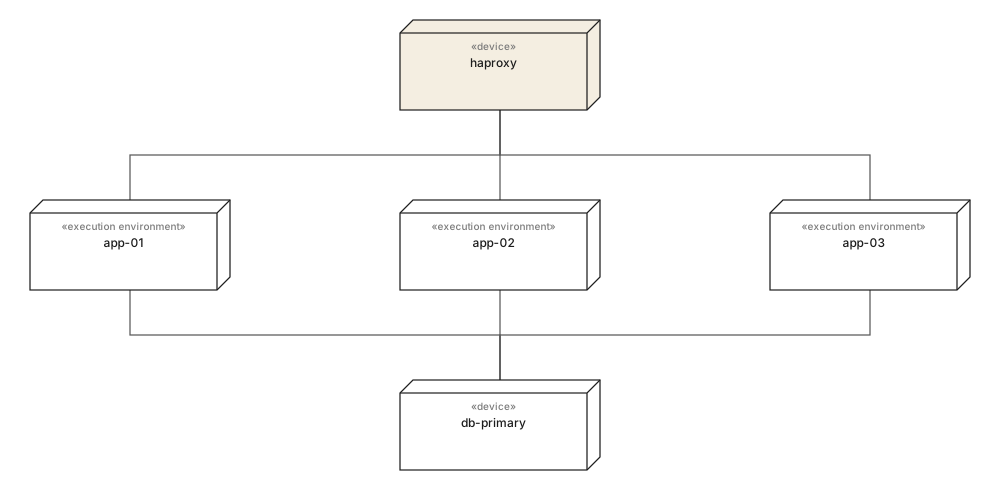
Tři aplikační uzly za jedním load balancerem, všechny zapisující do jediného primárního. Nakreslené takhle je jediné místo selhání vidět, aniž by ho musel někdo vyslovit: aplikační vrstva se vějířovitě roztahuje a datová ne. To je věta, na kterou někdo zareaguje, a nestála žádnou notaci navíc.
Když se počet za běhu mění, nahraďte ty tři uzly jedním, který nese násobnost - app-node [3..*] - místo kreslení libovolného počtu. Diagram, který tvrdí přesně tři, je nepravdivý při prvním škálování skupiny, a diagram, o kterém se ví, že je nepravdivý, přestane být konzultovaný.
04Co vynechat#
Každý diagram nasazení, který se stane zbytečným, se jím stane stejně: někdo pořád přidával uzly. Disciplínou je rozhodnout, k čemu diagram je, dřív než přibude druhý box.
Sáhněte po něm, když
- Protokoly a porty na každé komunikační cestě - je to obsah většiny posudků.
- Skutečné názvy artefaktů s verzemi, aby diagram odpovídal, co běží teď.
- Jedna reprezentativní instance na roli, s násobností, když se počet mění.
- Spravované služby jako obyčejná zařízení na okraji, s viditelnou hranicí toho, co provozujete.
Sáhněte po něčem jiném, když
- Logické vrstvy - nemají adresu a nic se na ně nenasazuje.
- Každou mikroslužbu ve velkém prostředí. Raději kreslete jeden podsystém na diagram.
- Monitoring, logování a CI agenty, pokud diagram není o nich.
- Živé počty instancí, které jsou v době posuzování diagramu už špatné.
Pokud potřebujete protějšek, který ukazuje software místo strojů, je to diagram komponent. Ty dva se obvykle kreslí jako pár a ten na nasazení je z nich kratší.
05Co si zapamatovat#
Po jednom řádku na každé
- 01Čtyři uzly, označené protokoly a pojmenované artefakty už jsou kompletním diagramem nasazení.
- 02Běžící kontejner je uzel; image, ze kterého se spustil, je artefakt. Záměna těch dvou je obvyklá kontejnerová chyba.
- 03Popisky protokolu a portu jsou tím, co dělá diagram hodným otevření při posudku.
- 04Kreslete jednu instanci na roli a použijte násobnost, když se počet za běhu mění.
- 05Pokud se na box nedá pingnout, na tenhle diagram nepatří.
06Časté dotazy#
Jaký je jednoduchý příklad diagramu nasazení?
Prohlížeč se připojuje na webový server, ten na aplikační server a ten na databázi, přičemž na každém je nasazen jeden artefakt. Čtyři uzly, tři komunikační cesty označené protokolem a tři šipky nasazení jsou úplný a užitečný diagram.
Jak nakreslit diagram nasazení pro Kubernetes?
Běhové části klastru modelujte jako uzly a obrazy jako artefakty. Load balancer je zařízení, ingress kontrolér a každý pod jsou běhová prostředí a obraz kontejneru je artefakt nasazený na pod. Spravované služby jako hostovaná databáze zůstávají zařízeními na okraji diagramu.
Jsou kontejnery v UML uzly, nebo artefakty?
Obojí, podle toho, který kontejner máte na mysli. Běžící kontejner je běhové prostředí, tedy uzel, protože v něm běží něco dalšího. Obraz, ze kterého byl spuštěn, je artefakt, protože je to soubor z buildu. Kreslit obraz jako uzel je nejčastější chyba kontejnerového diagramu.
Jak zobrazit redundanci na diagramu nasazení?
Buď nakreslete jednotlivé instance, což je poctivé, ale nefunguje nad čtyři, nebo nakreslete jeden uzel s násobností v rohu, například app-node s 3..*. Druhou možnost použijte, když se počet mění za běhu - diagram tvrdící přesně tři je špatně hned po prvním autoškálování.
Kolik detailu patří na diagram nasazení?
Tolik, aby odpověděl na otázku, kvůli které vznikl. Infrastrukturní přehled chce protokoly a porty na komunikačních cestách; onboardingový diagram chce čtyři boxy a nic víc. Každý další uzel je tvrzení, které musí někdo po další migraci udržet pravdivé.
V této sérii
- 01Co je UML?
- 02Symboly UML
- 03Výběr diagramu
- 04Diagramy tříd
- 05Příklady diagramů tříd
- 06Jak nakreslit diagram tříd
- 07Symboly diagramu tříd
- 08Sekvenční diagramy
- 09Příklady sekvenčních diagramů
- 10Jak nakreslit sekvenční diagram
- 11Diagramy případů užití
- 12Příklady případů užití
- 13Diagramy aktivit
- 14Příklady aktivit
- 15Stavové diagramy
- 16Příklady stavových diagramů
- 17Diagramy komponent
- 18Příklady komponent
- 19Kreslení diagramu komponent
- 20Symboly komponent
- 21Diagramy nasazení
- 22Příklady nasazení
- 23Diagramy objektů
- 24Diagramy balíků
- 25Diagramy složené struktury
- 26Komunikační diagramy
- 27Sekvenční vs komunikační
- 28Časové diagramy
- 29Diagramy přehledu interakcí
- 30Diagramy profilů
- 31UML pomocí AI
- 32Příklad e-shopu
- 33Příklad banky
- 34Příklad mikroslužeb
- 35Příklad AWS
Související články
Diagramy struktury
Diagramy struktury
Diagramy struktury
Praxe modelování
Diagramy struktury
Diagramy struktury